The member capacity for axial compression and for flexure is dependent on the spacing of elements which provide bracing along the length of a member. By default the program assumes that no bracing is provided along the length of the Physical Member. This is represented by the condition where the unbraced length field is shown as empty/blank.
Note
You may specify unbraced lengths as a fixed distance or by using RISA's Unbraced Length Commands. The unbraced lengths are:
The unbraced lengths that are used for member capacity calculations are listed in the Member Detail report after solution.
Note:
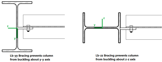
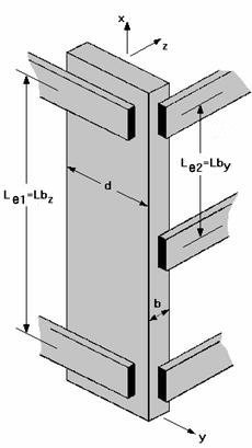
The Lb values: Lbyy and Lbzz, represent the distance between points which brace the member against Flexural (column-type) Buckling about the member's local y and z axes, respectively. Lb bracing prevents the entire member from moving laterally (perpendicular to its own axis). These Lb values are used to calculate slenderness ratios (KL/r) for both directions, which are used in the calculation of member axial compression capacity.
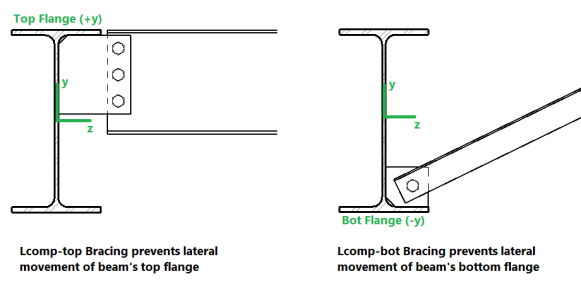
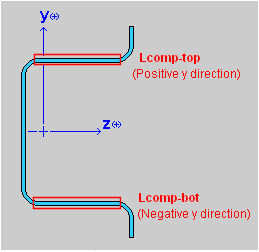
The Lcomp values, Lcomp-top and Lcomp-bot, represent the distance between points which brace the top or bottom flange of the member against Lateral-Torsional (beam-type) Buckling. These Lcomp values are used to calculate the member's flexural (bending) capacity. Where the top flange of the member is in compression due to bending, Lcomp-top is used. Where the bottom flange of the member is in compression due to bending, Lcomp-bot is used. Lcomp bracing prevents the member's flange from moving laterally (perpendicular to the member's axis).
Members which experience a moment reversal along their length (such as fixed-end or continuous members) have compression in both the top and bottom flange (although not simultaneously). The program uses the appropriate Lcomp (top or bottom) based on moment direction to calculate the bending capacity at each internal section along the member.
The top flange is the flange on the positive local y-axis side of the member. Therefore if a beam if rotated 180 degrees about its own axis (flipped upside down) the "top" flange will actually be facing downwards.
Note:
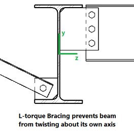
The L-torque value represents the distance between points which restrain the member against twisting about its own axis. This value is used to calculate the member's Torsional Buckling and Flexural-Torsional Buckling capacity. These limit states affect the member's axial compression capacity.
Note:
Aside from leaving the unbraced length blank or inputting a fixed distance, you can harness the program's ability to use a limited intelligence for determining unbraced lengths. In order to do this you can simply type in the name of the Unbraced Length Commands into the unbraced length field. If a valid command word is used then the program will accept and display that command in lieu of a distance value.
![]()
Some member types are pre-populated with an Unbraced Length Command when they are created. Below is a list of the commands which may be used:
When this command is used, all
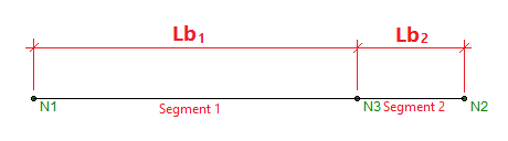
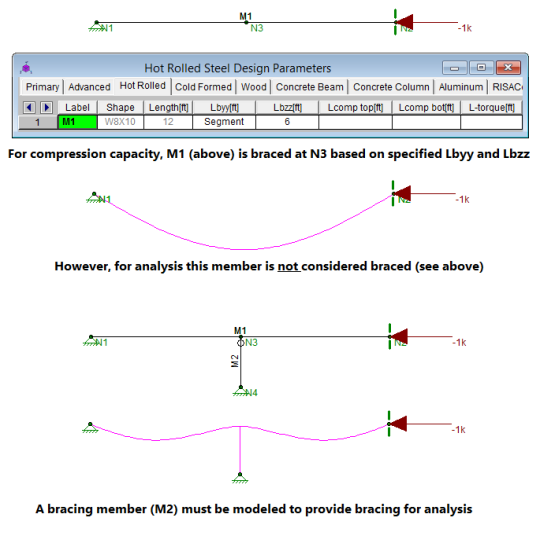
When using the Segment command the program will assume that each node along the length of the member can act as a brace location regardless of whether any bracing or restraint exists. In the example above this will result in an unconservative member capacity if no bracing will be supplied at N3 in real life.
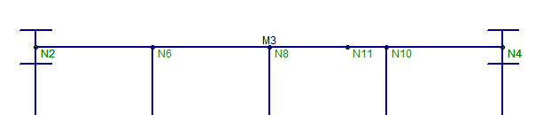
This command is only available for beam members in RISAFloor. This command works like the Segment command, except that only nodes which have another beam framing into them are considered brace points. In the example below, beam M3 is considered braced at N6, N8, and N10. N11 is ignored as a brace point since no other beam frames into M3 at N11. If the Segment command were used instead of Framing then N11 would be considered a brace point.
For Lcomp-top only, the unbraced length of the top flange is taken as the lesser of the Framing length and the Deck Unbraced Length.
When using the Framing command it is the user's responsibility to ensure that adequate bracing is provided by the framing and/or deck.
This command is only available for Lcomp-top and Lcomp-bot. When this command is used, the value entered for
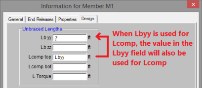
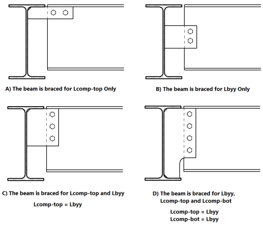
In the example below, Case C, the Lbyy command could be appropriately be used in the Lcomp-top field. In the example below, Case D, the Lbyy command could be appropriately used in both Lcomp fields. It would not be appropriate to use the Lbyy command for Case A or Case B below.
For RISAFloor models which are linked to RISA-3D models, if an unbraced length is set in RISA-3D, it is listed as 3D in the RISAFloor spreadsheets. This indicates that the unbraced length was set in RISA-3D, and that same value is being used in the RISAFloor model.
In general, the unbraced lengths for Cold Formed bending checks are based on the Lcomp value and axial checks are based on Lb values. Below describes more specifics based on the AISI 2012 code.
Lateral Torsional Buckling (AISI C3.1.2)
Lt = Lcomp
Lcomp is the unbraced length for the flange that’s in bending compression at that section (either Lcomp_top or Lcomp_bot).
This applies to all shapes and all AISI codes.
Note: Older Versions of RISA-3D (v12 and older)
Lt= smaller of Lbyy and Lcomp
When Lateral Torsional Buckling governs over local buckling, the display of the Seff in the Detail Report will report the Sc which is the elastic section modulus of effective section calculate relative to the extreme compression fiber at Fc.
Distortional Buckling (AISI C3.1.4)
Lm=Lcomp
Lcomp is the unbraced length for the flange that’s in bending compression at that section (either Lcomp_top or Lcomp_bot).
Axial Strength (AISI C4.1)
L= Could be Lbyy or Lbzz, whichever gives the larger of (KL/r)yy or (KL/r)zz
Flexural Torsional Buckling or Torsional Buckling (AISI C4.1.2)
Lt= L-Torque
Note: Older Versions of RISA-3D (v12 and older)
Lt= smaller of Lbyy and Lcomp
Distortional Buckling (AISI C4.2)
Lm= L-Torque
The Torsional Warping constant for Back-to-Back Channels and Tracks, Cw is calculated per the AISI prescribed doubly symmetric shapes (AISI-08 Manual 3.3.3) that are continuously welded (all the unbraced lengths are 0). If the Back-to-Back shape is not continuously welded (any of the unbraced lengths larger than zero), Cw is twice the value of each individual section.
For additional advice on this topic, please see the RISA Tips & Tricks website: www.risa.com/post/support. Type in Search keywords: Unbraced Lengths.
Effective Length Factors (K) are recommended or required for some design codes. The effective length factor allows you to adjust the unbraced length for Flexural Buckling as a simplified method of accounting for buckling effects. Kyy is a modifier factor for Lbyy. Kzz is a modifier factor for Lbzz.
If the K Factor field is left blank/empty then it is taken as 1.0, thereby not affecting the unbraced length.
If a value is entered for a K Factor, that value will be used for
Note
The Sway Flags indicate whether the member is to be considered subject to sidesway for bending about its local y and z axes. The y sway field is for y-y axis bending and the z sway field is for z-z axis bending. Click on the field to check the box and indicate that the member is subject to sway for that particular direction, or leave the entry blank if the member is braced against sway. These sway flags influence the calculation of the K factors as well as the Cm and Cb factors.
Sway flags are reserved for column members in RISAFloor and may be applied to any column segment at any floor level. However, when working in RISA-3D via RISAFloor, if a sway flag is checked for any segment of a physical column, the entire physical column will be assumed subject to sway. Beam members in RISAFloor are assumed to be braced against sway.